db-synth
Hardware
The db-synth hardware consists of a single PCB carrying an AVR DB series microcontroller in a DIP-28 package, a MIDI interface with optocoupler isolation, an analog signal output path using the on-chip DAC and opamps, and connectors for power, OLED display, and programming.
Overview
| Field | Value |
|---|---|
| MCU | AVR128DB28 or AVR64DB28 (AVR, 24 MHz) |
| Audio output | Internal 10-bit DAC, 48 kHz sample rate, 2.5V VREF |
| Signal conditioning | 2 internal opamps (unity gain buffer + 2nd-order reconstruction filter) |
| MIDI | Standard MIDI (31250 baud), optocoupler-isolated input (6N137), thru output |
| Display | SSD1306 OLED, I2C (address 0x3C) |
| Power | 5V DC via JST XH connector |
| PCB size | ~47 mm x 37 mm |
| PCB revision | 20240111 |
| License | Firmware: BSD-3-Clause, Hardware: CERN-OHL-S-2.0 |
PCB
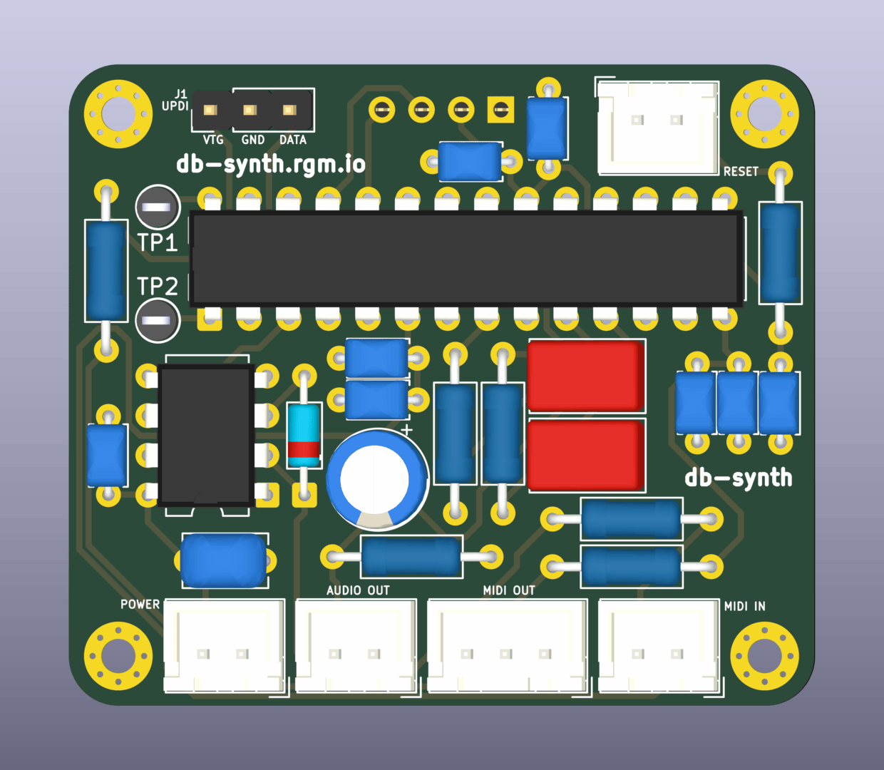
PCB top render
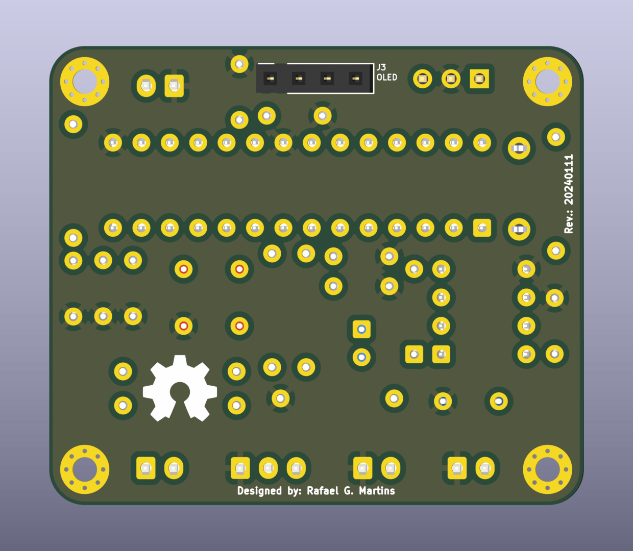
PCB bottom render
Resources:
KiCad source files are available in the repository under pcb/.
Connectors
All external connections use JST XH connectors, except for the UPDI programming header (standard 2.54 mm pin header) and the OLED display (2.54 mm pin socket).
| Connector | Type | Function |
|---|---|---|
| J1 | Pin Header 1x3 | UPDI programming |
| J2 | JST XH 2P | Reset |
| J3 | Pin Socket 1x4 | OLED display (I2C) |
| J4 | JST XH 2P | Power (5V) |
| J5 | JST XH 2P | MIDI IN |
| J6 | JST XH 3P | MIDI OUT/THRU |
| J7 | JST XH 2P | Audio OUT |
MCU selection
The PCB schematic references the AVR64DB28, but the AVR128DB28 is pin-compatible and also supported. The MCU must be selected at firmware build time via the WITH_MCU CMake option. Both variants are available in SPDIP-28 (DIP) package, making them easy to hand-solder or socket.
Enclosure
A 3D-printable enclosure designed in OpenSCAD is available. It consists of a front shell with cutouts for the OLED display and side-mounted connectors, and a back cover.

Enclosure front shell

Enclosure back cover
| Part | File |
|---|---|
| Front shell | enclosure-front.stl |
| Back cover | enclosure-back.stl |
Source files are available in the repository under 3d-models/.
Build manual
For general assembly instructions -- including PCB ordering, parts sourcing, soldering, and UPDI flashing -- refer to the Hardware Build Manual.
The board is primarily PTH components. The only IC that requires special attention is the 6N137 optocoupler (DIP-8). Consult the Interactive BOM and the Schematic (PDF) for component placement and values.
- For firmware building and flashing instructions, see Firmware.
- For the complete MIDI implementation chart, see MIDI implementation.